By Mike Marsh
|

|
|
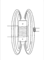
Photo by Trolley Scan (Pty) Ltd. |
RFID SYSTEMS
RFID transponder systems comprise transponders (often called tags) and readers. The tags are attached to the goods to be identified and the reader is usually attached to a computer network which processes the identification data.
Passive RFID transponders operate on radiated energy from the reader, while active transponders have their own battery source in the transponder to provide the energy needs of the electronic circuits on the transponder. Obviously passive transponders will be much cheaper to produce than active transponders as they are much simpler. Generally passive transponders comprise just a single integrated circuit mounted on a simple antenna. As cost is a major driving force in the commercial viability of RFID, the interest is in improving the performance of passive RFID systems.
TRANSFER OF ENERGY
Passive transponders use energy transferred from the reader via the antennas to power up their circuits.
Energy propagates through the air and through conductors in the form of a combination of magnetic signals and electric signals. Transferring the energy from the wires and electronic circuits to the air to travel towards the transponder and then to be collected at the transponder side and transferred to its wires and circuits, is done by a structure called the antenna. The electric components of the signals are much more effective in travelling through air over longer distances than magnetic signals. However, antennas for electric signals have a size issue, as in order for them to be very efficient, they need to be approximately half the wavelength of the operating frequency in physical dimension. This means that at frequencies below 100 MHz , the antennas for electric propagation mode are physically too large to be practical for the application of RFID, and even at the preferred frequencies of UHF RFID (860 MHz to 960 MHz), they still have dimensions in the order of 160 millimetres. This physical size restriction means that at frequencies below 100 MHz, magnetic propagation modes are used, while above 100 MHz, electric fields are used.
PROPAGATION OF ENERGY FIELDS
In order for a transponder to receive energy from a reader, it must reside inside the energy field of that reader.
Magnetic fields are the lines of force that flow between the North and South pole of a magnet. From experiments at school, one might remember the iron filing experiment where a piece of paper covers a bar magnet and iron filings sprinkled on the paper show the lines of force. These lines do not extend far beyond the axis of the magnet. One way of increasing the distance from the axis is to increase the length of the magnet or the spacing of the North and South poles which means a bigger reader antenna. The generation of the fields of the magnet is done via coils providing alternating current signals at the frequency of operation. The limiting strengths are due to the coils needing high voltages to generate these fields and their insulation breaking down. Despite all these developments, range from magnetic systems is seldom ever greater than one metre.
Electric fields are generated in the transmitter and are launched into air via the antenna system. From launch they travel away from the transmitter antenna at the speed of light, radiating in all directions and at any instant, spreading their energy over the surface area of a sphere of radius of the time since launch multiplied by the speed of light. These signals radiate in a straight line indefinitely, and for example could even be detected by an observer on the moon. As the surface area of the sphere is increasing with distance travelled, every doubling of distance means a four times increase in surface area, or that the energy density of the wave is only 25% of the density of the wave at half distance.
Hence operating range for passive transponders becomes a function of efficient collection of this energy arriving at the transponder, and of how small an amount of energy the transponder will need in order to be able to operate. Practical distances for electric field passive transponders are up to about 15 metres, depending on the operating frequency which has a major impact and which will be covered later.
MAGNETIC COUPLED TRANSPONDER SYSTEMS
|
|
|
Figure 1. Low frequency transponders use coils to couple the energy via magnetic fields. (Source: Trolley Scan (Pty) Ltd.) |
The preferred operating frequencies for transponders in the magnetic coupled mode is 125 KHz (to 134 kHz) and 13.56 MHz. In addition some systems operate at 8.1 MHz. 125 kHz transponders were the first series available in a single chip format. A very small version packaged in a glass tube, just 11 millimetres long and 1.5 mm in diameter, was developed in the early 1980s as a device to positively identify race horses for handicapping purposes. The reason 125 kHz was chosen is that it was below the minimum operating frequency that was controlled by the FCC in the USA, and as a result the devices could be marketed free from any radio regulations. At the time of this transponder’s development, the semiconductor industry still treated analogue designs separately from digital designs, and their technology had frequency limits for integrating different functions, meaning they did not want to push any higher the operating frequencies of such early transponders.
In order to couple sufficient energy into the transponder from the weak magnetic fields, the transponders have coil antenna systems comprising up to 1,000 turns of very fine wire. The difficulty in making this antenna means that manufacturing costs are relatively high, production volumes are low and the transponder is hence expensive.
The read range of such transponders is about 20 millimetres, meaning that they are suitable for identifying items, bodies, etc., when the reader is just about in contact with the transponder. As the transponders are small and use magnetic fields, they can be placed inside a body, or even a lump of metal, as long as they can be orientated along the lines of flux. This is the chip that is used to label pets, in car keys for ignition systems, labelling gas bottles, in bolus tags in herd animals, on the feet of athletes when timing them crossing the mats in sports events and in situations where conventional labelling can’t work due to dirt, mud, grease and other obstructions for written and printed labelling systems. In South Africa, these tags have been used in metal mine props 6,000 ft below the surface of the ground to identify the metal props being used as an asset identification aid. This is the same chip that some companies in the U.S.A. are embedding into their staff as a positive identification aid.
These are the most common transponders available today, manufactured by a wide range of suppliers.
Since 1998 a new series of magnetic coupled tags has been available which operates at 13.56 MHz, needing far fewer turns than the 125 kHz transponder antenna and hence cheaper to manufacture. The tags comprise a small coil of a few turns, often etched on the outer edges of a credit card-sized flexible printed circuit substrate, and to which a single chip is bonded. These transponders are typically the size of credit cards but might be as small as 1.5 cm by 1.5 cm in area. They couple their energy to the reader via magnetic propagation. By the reader continuously providing an energising field, which can be modulated, the tags can extract energy and data from the reader and communicate back to the reader. Such tags often have read/write capabilities and often anti-collision properties to allow for many tags to be in the reader beam at the same time. The reading and writing distance of such tags is limited by the magnetic means of propagation to typically 50 cm, but some manufacturers claim 1 metre operating range.
ELECTRIC COUPLED TRANSPONDER SYSTEMS
|
|
|
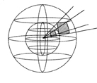
Figure 2. Electric field energy radiates from the source at the speed of light, spreading this energy in all directions. Every doubling of distance spreads the energy over four times the area reducing the energy density available. (Source: Trolley Scan (Pty) Ltd.) |
Electric field passive tags generally operate in the 860-960 MHz bands and at 2.45 GHz. In addition there are systems that operate in the 434 MHz band.
Earlier in the article, we described how electric field energy radiates from a point source out to infinity, travelling at the speed of light. That mode of propagation applies to all the frequencies mentioned above. What does change with operating frequency, is the dimensions of the antenna system needed to launch and receive the signals, and the collecting area of the transponders around their antennas which enable the transponder to capture some of the passing energy and convert it to electrical power for operating the transponder.
The wavelength of the radio wave is equal to the speed of light divided by the operating frequency. At 100 MHz, the wavelength is 3 metres, at 915 MHz it is 0.32 metres and at 2.45 GHz it is 0.12 metres.
For an antenna to operate efficiently, it needs to have dimensions that are approaching half of a wavelength. This implies that as you increase the operating frequency, so the physical size of the antenna will reduce linearly with increased frequency.
The other important criteria is the capturing area of the antenna, known as antenna aperture. The aperture represents the area on the sphere of radius equal to the distance from the source, where all the energy passing through that area will be converted to power for the transponder. Think of this as the area of a photocell collecting energy from a light source. The larger the area, the more energy it will collect, and the more energy will be available to power up the transponder.
The aperture is proportional to the square of the wavelength meaning that at higher frequencies the aperture becomes very small. For a dipole, at 868 MHz the aperture area is 149 sq cm, at 915 MHz it is 134 sq cm and at 2.45 GHz it is 18 sq cm.
This means that to send the same operating energy to a transponder at 2.45 GHz, you need more than 700% of the power you would need to operate the same transponder if it operated at 915 MHz. As a result, it is practical to get operating ranges of 15 metres for an 860 to 960 MHz transponder, but only a couple of metres at 2.45 GHz.
Due to this shrinking aperture, in practice passive transponders do not operate at frequencies higher than 2.45 GHz. Above this frequency, transponders are active, using batteries to supply their power needs.
One can see from the above explanation, that the 860 MHz to 960 MHz frequency band is the best compromise between operating range, low power transmissions and antenna size for passive RFID. This fact has slowly been realised by the regulatory bodies around the world and we now have the situation where almost every country in the world has allocated some frequency within this band for their future RFID needs.
A disadvantage of UHF systems is that it the signals cannot penetrate metal surfaces or water. However the signals do reflect very well off the metal/water/hard surfaces whichallow the signals to bounce around and to get to the difficult to reach protected corners.
FREQUENCY AGILITY
|
|
|
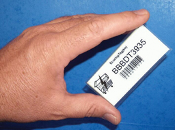
A UHF passive transponder reduced to credit card size and having an operating distance up to 13 meters (Photo by Trolley Scan (Pty) Ltd.) |
As the frequency bands are over-used at the ideal UHF spectrum with other users of radio frequency applications, it was not possible to have a global frequency for RFID. The regulators of the individual countries have allocated different frequencies near the ideal frequencies for passive UHF RFID. This has meant that the transponders need to operate over 100 MHz of bandwidth so that all goods labelled with transponders in any one country could be read by readers operating on a different frequency in any other country. This property is known as frequency agility. Modern UHF transponders based on dipole antennas have 100 MHz-wide frequency agility allowing them to be used in all countries in the world.
UHF transponders generally use the invention of the backscatter modulation principle to transmit data back to the reader. This has resulted in it being able to have all its features incorporated into integrated circuits with wide manufacturing tolerances, meaning that electric field type tags in a read-only mode can be made extremely cheaply. Such a tag would be passive, have no onboard tuned circuits, be read-only, consist of a single integrated circuit and a simple antenna, operate at any of a range of frequencies, be temperature insensitive, and broadcast a large data value when illuminated by a reader’s energising field. In such a system the reader is complex because it provides the frequency stability, the energy of the system and the receiver selectivity to receive the weak return communications, but the tags are very cheap. This is ideal for the situations where there is one reader and many tags.
MULTIPLE TRANSPONDER SITUATIONS
As the operating range of the transponder systems increases, so it becomes more likely that at least two transponders will be in the reading zone at one time.
Transponders and readers implement a protocol between the parts of the system to cater for the situation where many transponders are in the reader zone at one time. In most transponder systems the protocol works based on the requirement that each transponder has a unique identity number to differentiate one transponder from another. For applications in the retail sector where RFID is being used to replace the existing barcode numbering system, the unique ID is a disadvantage as the barcode numbering system in place is based on the fact that each product range from each manufacturer has a unique number, and that all identical products have the same identity number. There are protocols such as Trolleyponder and Supertag where all the transponders can have the same identity and the reader can accurately count the number of these transponders in this zone. This will become an issue later when RFID systems are produced in sufficient volumes to become a viable replacement of barcode systems for retail applications.
Electric field tags are available in many different configurations and price ranges, particularly dependant on the complexity of the transponder. If the transponder is a read/write transponder it will usually have a read distance that is much greater than the distance at which it can be written. This is due to the fact that the energy requirements for the write operation are higher than those needed for the read operation, and as explained above, energy requirements have an impact on range. For this reason most UHF transponder systems are read-only.
Mike Marsh is Managing Director of Trolley Scan (Pty) Ltd. (www.trolleyscan.com) and President of RFID Technologies CC.
For more information, please send your e-mails to swm@infothe.com.
ⓒ2007 www.SecurityWorldMag.com. All rights reserved.
|